Link Media Redundancy – Advanced Enterprise Campus Design
2 min read
In mission-critical applications, it is often necessary to provide redundant media.
In switched networks, switches can have redundant links to each other. This redundancy is good because it minimizes downtime, but it can result in broadcasts continuously circling the network; this is called a broadcast storm. Cisco switches implement the IEEE 802.1d spanning-tree algorithm, which aids in avoiding the looping that occurs in broadcast networks. The spanning-tree algorithm guarantees that only one path is active between two network stations. The algorithm permits redundant paths that are automatically activated when the active path experiences problems.
You can use EtherChannel to bundle links for load balancing. Links are bundled in powers of 2 (for example, 2, 4, 8) groups. EtherChannel aggregates the bandwidth of the links. Hence, two 10 Gigabit Ethernet ports provide 20 Gbps of bandwidth when they are bundled. For more granular load balancing, use a combination of source and destination per-port load balancing, if available on the switch. In current networks, EtherChannel uses Link Aggregation Control Protocol (LACP), which is a standard-based negotiation protocol that is defined in IEEE 802.3ad. (An older solution included the Cisco-proprietary PAgP protocol.) LACP helps protect against Layer 2 loops that are caused by misconfiguration. One downside is that it introduces overhead and delay when setting up a bundle.
Redundancy Models Summary
Table 7-6 summarizes the four main redundancy models.
Table 7-6 Redundancy Models
| Redundancy Type | Description |
| Workstation-to-router redundancy | Uses HSRP, VRRP, GLBP, and VSS. |
| Server redundancy | Uses dual-attached NICs, FEC, or GEC port bundles. |
| Route redundancy | Provides load balancing and high availability. |
| Link redundancy | Uses multiple links that provide primary and secondary failover for higher availability. On LANs, uses EtherChannel. |
Large-Building LANs
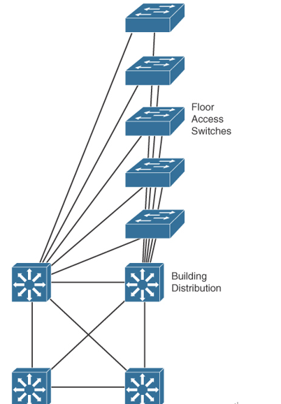
Large-building LANs are segmented by floors or departments. The building-access component serves one or more departments or floors. The building-distribution component serves one or more building-access components. Campus and building backbone devices connect the data center, the building-distribution components, and the enterprise edge-distribution component. The access layer typically uses Layer 2 switches to contain costs, with more expensive Layer 3 switches in the distribution layer to provide policy enforcement. Current best practice is to also deploy multilayer switches in the campus and building backbone. Figure 7-11 shows a typical large-building design.

Figure 7-11 Large-Building LAN Design
Each floor can have more than 200 users. Following the hierarchical model of building access, building distribution, and core, Fast Ethernet nodes can connect to the Layer 2 switches in the communications closet. Fast Ethernet or Gigabit Ethernet uplink ports from closet switches connect back to one or two (for redundancy) distribution switches. Distribution switches can provide connectivity to server farms that provide business applications, Dynamic Host Configuration Protocol (DHCP), Domain Name System (DNS), intranet, and other services.
For intrabuilding structure, user port connectivity is provided via unshielded twisted-pair (UTP) run from cubicle ports to floor communication closets, where the access switches are located. These are Gigabit Ethernet ports. Wireless LANs are also used for user client devices. Optical fiber is used to connect the access switches to the distribution switches with new networks utilizing 10 Gigabit Ethernet ports.


